


 Casa /
Il viaggio era proprio sulla carta: Perché un cric a vite si ferma ancora bruscamente
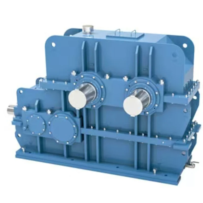
Cambio del mixer interno in gomma: Leggi il profilo di caricamento batch, Non solo kW del motore
22 ottobre, 2026
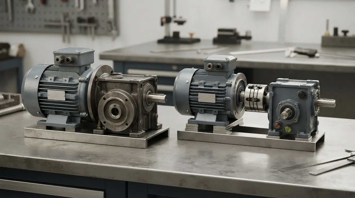
Accoppiamento del cambio industriale caldo dopo l'allineamento a freddo: Cosa controllare
22 ottobre, 2026
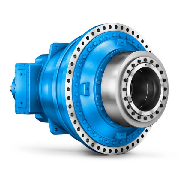
Il motore idraulico a ruota non ruota: Motore separato, Guasti ai freni e al cambio
22 ottobre, 2026
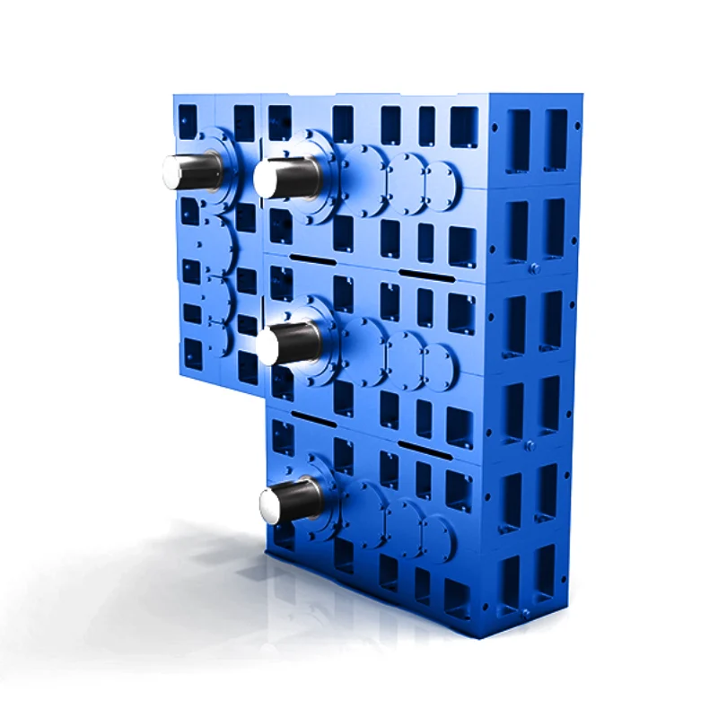
Cambiamenti del gap del rullo del calendario: Cosa deve contenere l'accoppiamento di trasmissione?
22 ottobre, 2026
A screw jack installation that reaches its limit switch early, or drives into a mechanical stop before the switch ever trips, is one of those faults that sends people back to the drawing with the arithmetic in hand. The arithmetic is usually correct. The part that was never checked is which travel the arithmetic describes.
Three different quantities get called "infarto" in a screw jack installation, and they are not the same number. Working out which one the calculation produced, and which one the machine actually has available, resolves most of these cases without touching the hardware.
From Rotation to Linear Travel
Start with the kinematics, because it is the one part that is unambiguous.
Linear speed at the screw equals input speed divided by the reduction ratio, multiplied by the lead:
*v* = (*n*in / *i*) × *L*
where *n*in is input speed in rpm, *i* is the gear ratio, and *L* is the lead in millimeters per revolution.
Time to cover a given distance is that distance divided by the linear speed, with the speed converted to mm per second.
A worked example
Take a jack with an 8 mm lead, driven by a four-pole motor at 1450 rpm through a worm reduction that offers a normal ratio of 6:1 and a slow ratio of 24:1.
Normal ratio:
- Linear speed: (1450 / 6) × 8 = 1933 mm/min, or 32.2 mm/s
- Time for 500 mm of travel: 500 / 32.2 ≈ 15.5 s
Slow ratio:
- Linear speed: (1450 / 24) × 8 = 483 mm/min, oppure 8.06 mm/s
- Time for 500 mm of travel: 500 / 8.06 ≈ 62 s
Both results are correct, and both describe a quantity the machine may not be able to use. The figures above are demonstration values for the arithmetic, not parameters of a particular unit; the ratios and lead on your machine will be different, and the method is what carries over.
Look at what the formula contains. There are two independent variables besides input speed: the ratio and the lead. Knowing the ratio without the lead gives you nothing. Knowing the lead without the ratio gives you nothing. And both are properties of the specific unit, not of the series. A supplier quoting "6:1" has told you one of two numbers you need.
There is a third thing the formula assumes, and it is the one that causes most of the trouble. The input speed is not the motor's synchronous speed once the motor is under load. A four-pole induction motor at no load runs near 1500 rpm; at rated load it runs near 1450; at 60 Hz versus 50 Hz supply it is different again; and on a variable frequency drive it can be anything within the programmed range. The travel calculation is only as good as the speed figure put into it.
The ratio itself is worth noting as a design constraint. Worm screw jacks are typically offered in a small number of discrete ratios, a normal ratio and a slow ratio being a common arrangement, with the exact set depending on the series. There is no continuous adjustment. If the required speed falls between the two, changing it means changing the input speed, adding an intermediate stage, or accepting one of the two.
The Machine May Not Move the Part You Think It Moves
The second source of error is structural, and it changes where the limit switches go.
Screw jacks come in two configurations, and the difference is which element travels.
In a translating screw Progetto, the worm wheel is threaded onto the screw. When the wheel turns, the screw is driven axially through it. The screw moves; the worm wheel stays put in the housing. That translation does not happen on the thread alone: it requires the screw to be held against rotation, usually by an anti-rotation feature at the working end or by the way the load is guided, because a screw that is free to rotate will simply turn with the wheel instead of advancing through it. The load is attached to the end of the screw, and the screw's exposed length changes as it travels.
In a traveling nut Progetto, the worm wheel is keyed to the screw so the screw rotates but does not translate. A separate nut rides on the screw and moves axially along it. The load is attached to the nut. The screw's position is fixed; the nut's position changes.
These are both legitimate arrangements, and from the outside, at the point where the load attaches, they look similar. They are not interchangeable in installation terms.
The consequence for travel is direct. In the translating design, the traveling element is the screw, and its full extension is limited by how much thread remains engaged in the worm wheel. In the traveling nut design, the traveling element is the nut, and its range is limited by the threaded length of the screw and by where the nut body can physically go before it meets the housing or the end bearing.
A travel figure quoted for one configuration does not describe the other. This is the most common way a jack arrives on site with the "A destra" stroke and does not perform as expected: the quotation was written against one configuration and the machine was built in the other.
Mounting Arrangement Determines Which Thread Is Useful
Within each configuration there is a further choice, usually designated by a letter in the model code, that sets which end of the screw is the working end and which direction the load moves.
For a translating screw jack, the working end of the screw can be arranged to extend upward or downward. For a traveling nut jack, the nut can bear on the load from above or pull from below, again with the screw's working end either up or down.
The practical meaning is that the same nominal stroke can be arranged four different ways, and in each arrangement a different portion of the screw thread is the useful portion. Some thread is inside the housing at all times, some is dedicated to the end fitting, and some is taken up by the anti-rotation device if one is fitted.
Three Travels, and Only One of Them Is What You Need
This is where the discrepancy usually lives.
Theoretical travel is what the formula gives you: linear speed multiplied by available running time, or simply the thread length that exists.
Nominal travel is the figure in the catalog and on the quotation. It usually refers to a standard stroke length in the series, measured between defined reference points on the unit itself.
Usable travel is what the installed machine can actually traverse, and establishing it starts with the nominal figure rather than with a subtraction. The first question about the nominal stroke is what it is referenced to and what it already accounts for: on some units the published figure is measured between defined reference faces on the housing and the shaft, and on others it is already the working travel, with the minimum thread engagement and the end-fitting length taken out. Applying a deduction the manufacturer has already applied is how a machine ends up with less travel than it was designed around.
That check done, what remains to be established is external to the jack:
- the thread length that must remain engaged in the worm wheel or nut at full extension, where the manufacturer's figure has not already been built into the nominal stroke,
- the length occupied by the end fitting, rod end, or clevis at the working end, where that is not inside the nominal figure,
- the space taken by any anti-rotation arrangement, bellows, or protective cover,
- the clearance needed to reach the limit switch before the mechanical stop, e
- any allowance for the structure the jack is mounted to, which may not permit the full nominal stroke to be used even though the jack can produce it.
The last of these is a property of the installation rather than of the jack itself, and it is the one nobody puts on a drawing.
A jack with 500 mm nominal stroke installed in a frame that only allows 430 mm of movement will run out of frame before it runs out of jack. The limit switch, set from the nominal figure, never trips. The structure takes the load instead.
Sizing the Load Correctly Is Part of the Travel Question
There is a second reason a jack stops short of where it should: it is not short of stroke, it is short of force, and it stalls.
The force a jack must produce is not just the weight it is lifting. It is the sum of the static load, the force needed to accelerate that mass, the friction in the guidance, e, in a vertically mounted unit, the weight of the screw itself, which in a long-stroke translating design can be a meaningful fraction of the total.
Friction in the guidance is the term most often left out. How much it adds depends on the guide type, the guide manufacturer's own friction data for that product, how the guide is lubricated and maintained, and how the load is distributed across it, and those inputs vary enough between installations that no single percentage figure can be carried from one machine to another. What a sizing calculation needs is the coefficient or the friction force the guide manufacturer publishes for the specific guide, applied to the actual normal load in that arrangement, and where that data is not available, a measurement on the machine itself. A jack specified against the payload alone and installed on a sliding guide is a jack that is undersized by an amount nobody calculated, and the symptom is a unit that moves slowly, heats up, and occasionally fails to complete the stroke.
There is a way to get a rough handle on that number without a friction table or a force gauge. Time the stroke twice on the same machine, once with the load and once without it, at the same commanded speed. The difference in travel time between the two runs reflects the friction and acceleration term together, and it is measured on the machine that has to live with it, which beats a coefficient from a handbook written for a different guide. It is not a clean friction figure, and the test only works on a drive that holds speed against load. Where the controller closes the loop on speed, a heavier load is answered with more torque and the stroke time may barely change, so a small difference must not be read as a small friction term. In that case the drive load itself is the measurement, and the clock is not. This test also cannot stand in for a force or torque calculation: it indicates, it does not size the unit.
Acceleration matters too. A jack moving a large mass through a short stroke at high speed spends a significant part of its cycle accelerating and decelerating, and the peak force during acceleration can exceed the static load substantially. The peak, Non la media, is what the unit must survive.
Self-Locking Is Not a Brake
One more point belongs here because it gets assumed in exactly the situations where travel matters most.
Whether a worm gear screw jack self-locks depends on its lead, its efficiency, Il carico, and the configuration, and some classes of jack do not self-lock at all. It cannot be assumed from the family name, from the ratio, or from the fact that a similar unit did; it has to be confirmed against the documentation for the specific model and the specific lead. Where a unit is self-locking, the load will not back-drive the screw when the motor stops. That is a real and useful property. It is not a safety function.
Manufacturers of worm gear units state explicitly that a self-locking unit must not be subjected to large reverse inertia torques from the load side, because the self-locking property does not imply the ability to absorb that energy without damage. A load that is coasting, or a mechanism that can be pushed by an external force, puts torque into the jack through the output rather than the input. Self-locking resists slow back-driving; it does not manage an impact.
For a vertically mounted jack holding a load over people or over equipment, the holding function belongs to a mechanical brake, a counterbalance, or a mechanical retainer, and the limit system belongs to the control system. Treating self-locking as the last line of defense is a design error that only shows up once.
Setting Up the Travel Envelope
The envelope drawing is the same document a supplier needs, whatever the outcome of it is. Where the arrangement turns out to be a worm gear screw jack, il SWL worm gear screw reducer range is the family this discussion maps onto, and the figures that decide the selection are the ones already on that sheet rather than anything on a catalog page.
The practical output of all this is a single drawing, and it is worth making before the jack is ordered rather than after it is installed. One sheet, one scale, with the following established for the specific unit and the specific installation.
| Element | Cosa stabilire |
|---|---|
| Total mechanical stroke of the unit | From the manufacturer, for the specific configuration |
| Required engagement at full extension | Manufacturer's minimum, at rated load |
| End fitting and attachment length | Both ends, including any clevis or rod end |
| Anti-rotation or protective hardware | Its travel-occupying length |
| Structural clearances at both extremes | Frame, guard, adjacent equipment |
| Limit switch positions, mechanical and electrical | Set from the usable travel, not the nominal travel |
| Mechanical hard stop position | Must be reached only after the electrical limit, never before |
| Overtravel allowance | Distance between electrical trip and hard stop |
| Loading direction and guidance type | Determines the friction term in the force calculation |
| Required speed and the ratio that produces it | With the actual motor speed under load, not the synchronous figure |
The two lines that prevent the common failures are the seventh and eighth. The electrical limit must trip with margin before the mechanical stop is reached, and that margin has to be preserved at the installed position, not just on the bench. If the mechanical stop is what the machine hits in normal operation, the limit switch is decoration.
The Two Numbers That Get Put In Wrong
Every travel calculation is arithmetically correct. When a jack stops short or drives into a hard stop, the mistake is in what went into the formula, and in practice it is nearly always one of two figures.
The first is the input speed. The calculation is done at 50 Hz and 1500 rpm, and the motor under load at the actual supply frequency is running slower than that. The travel still happens, it just happens later than the calculation said, and a cycle that depended on 15 seconds of movement now needs more. On a variable frequency drive the error goes the other way as easily: the figure used is the maximum programmed speed while the process runs the motor below it. The linear speed is proportional to input speed, so a 5 percent error in the speed figure is a 5 percent error in the stroke time. What that error does to the machine depends on how the travel is stopped. A limit switch triggered by position is not affected by speed error at all: the jack arrives at the same place, just later than the calculation said. A stop commanded on time is affected directly, because the distance covered in that time is proportional to a speed that was never the figure on the nameplate. That is where a 5 percent error becomes a real travel error rather than a scheduling one.
The second is the configuration. A stroke figure quoted for a translating screw does not describe a traveling nut unit of the same nominal size, because in one the screw travels and in the other the nut does. The two arrangements look alike where the load attaches and behave differently in every dimension that matters: which thread is working, how much must stay engaged, where the limit switches are set. A jack ordered against a stroke figure without the configuration named is a jack ordered against whichever arrangement the quotation happened to assume.
Both errors are caught by the same drawing, and the point of drawing it before the order is that neither error is visible in a catalog. The envelope table above is the whole checklist; the two figures that go into a calculation wrong are a motor speed read off a nameplate instead of measured under load, and a stroke that belongs to a configuration other than the one being built.
One sheet, drawn to scale, with the actual motor speed under load written on it. The travel question is settled there or it is not settled at all. The alternative is finding out in the field, with a stalled jack, a loaded structure, and a limit switch that never tripped.
If the sheet already exists, the selection conversation is short: the specific model being considered, the lead, the travel and limit drawing, the actual load, and the motor speed under load. That set is what the contact page needs to turn a travel envelope into a configuration.
Condividi sui social:


Contattaci
In questo articolo
Cambio del mixer interno in gomma: Leggi il profilo di caricamento batch, Non solo kW del motore
22 ottobre, 2026
Accoppiamento del cambio industriale caldo dopo l'allineamento a freddo: Cosa controllare
22 ottobre, 2026
Il motore idraulico a ruota non ruota: Motore separato, Guasti ai freni e al cambio
22 ottobre, 2026
Cambiamenti del gap del rullo del calendario: Cosa deve contenere l'accoppiamento di trasmissione?
22 ottobre, 2026